
From drawing to controlled output.
ELV Tools Suite is an emerging desktop environment designed to reduce repetitive work and manual error between CAD design, rack composition, cable scheduling and engineering documentation.
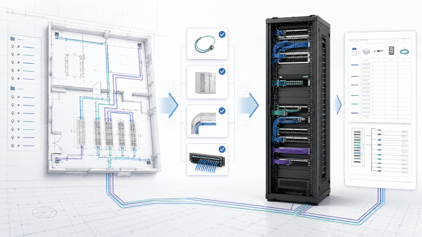
Automation under designer control.
The suite is intended to interpret disciplined drawing conventions without demanding unnecessary drafting work. Recognition supports the engineer; validation remains explicit.
Project setup
Define floors, racks, capacities and naming rules.
DXF analysis
Route cable geometry using authoritative rack prefixes.
Rack assembly
Allocate validated circuits to physical rack equipment.
Deliverables
Review cable schedules and item take-offs before export.
Time is saved where designers repeat work.
ELV Tools Suite targets high-friction activities without removing designer control. Exact savings will be measured during pilot projects; the bars indicate relative automation opportunity, not performance claims.
Replace repeated manual counts with structured DXF intake and rack-prefix routing.
Calculate from drawing geometry and declared riser logic; flag incomplete paths instead of guessing.
Update allocated and remaining quantities as the designer assigns individual cables.
Reuse validated project data rather than transcribing it into separate documents.
Independent tools. Shared project intelligence.
Each application can operate independently or continue through a common pipeline. Manual and imported data remain editable by the designer.
Shape Finder
Recognize, review and validate device candidates.
Cable Schedule
Measure runs, resolve rack routing and preserve endpoints.
Rack Assembler
Compose equipment and allocate cables per port.
Document Composer
Verify and generate CIS, Take-Off and BOQ outputs.
Recognition with human validation
Geometry, proportions, angles, surfaces and colours generate candidates.
- Accepted, excluded and pending-review records
- Device Take-Off output
- Standalone export or pipeline hand-off
Traceable cable outcomes
Reads rack-prefixed layers, measures polylines and associates endpoints.
- Same-floor and remote-floor length logic
- Shortest-to-longest deterministic order
- Incomplete riser data flagged without guessing
Content before enclosure
Designer-owned warehouse items are composed before final rack capacity is selected.
- Multi-system and multi-floor allocation
- Per-port traceability
- Automatic remaining-quantity updates
Verified outputs
Approved cable, item and rack records feed the pre-export review.
- Cable Installation Schedule
- Device Take-Off
- BOQ and live Excel formulas
One controlled path from geometry to documentation.
The suite is conceived as a desktop engineering environment with separated data, composition and document-generation responsibilities.
Rack routing is governed by authoritative layer prefixes; suffixes retain system classification.
Floors, racks, equipment, detected circuits and designer assignments remain structurally distinct.
Designers place warehouse-defined equipment and allocate validated circuits with deterministic remaining counts.
Cable schedules and optional item take-offs pass through a dedicated pre-export control interface.
Geometry can propose associations; uncertain detections remain subject to explicit designer confirmation.
Built with working engineers.
We are looking for a small number of ELV consultancies, system integrators and CAD-led engineering teams willing to test real project workflows and help validate the product boundary.
Real drawings
Anonymised test cases with known engineering outcomes.
Validation
Review false positives, exceptions and workflow friction.
Field reality
Ensure outputs remain useful to designers and installers.
Integration
Explore practical interoperability without vendor lock-in.